GEOMEMBRANES (Educational Research)
Submitted by Hong Yin, Xinli Liu and Unchin Cho
INTRODUCTION
Geomembranes are thin, two-dimensional sheets of material with very low permeability. Geomembranes are flexible and are manufactured from synthetic or bituminous products. They may be strengthened with a fabric or film. Materials which fulfill the same function but which are composed of other substances are not considered to be geomembranes, examples of such materials are steel or concrete barriers, sealant layers of asphaltic concrete, bentonite, and mixtures of soil and clay. The basic difference between geomembranes and geotextiles is that geomembranes have very low permeability, while geotextiles have about the same permeability as sand. In comparison to geomembranes, applications of geotextiles in civil engineering are relatively new, which includes one important application-the protection of geomembranes (1).
To all intents and purposes geomembranes may be considered to be impermeable to both gases and fluids. This makes them ideal for forming waterproof or gasproof barriers between adjacent bodies of soil or soil and fluid. Geomembranes are mainly applied to protect groundwater from contamination by permeation of leachate, specific practical applications are in municipal garbage dumps, sewage ponds, hazardous waste landfills and industrial holding ponds. The function of the geomembrane in these cases is to form a barrier between the water and the surroundings, and to ensure that water transport through the geomembrane is reduced to a minimum. Other geomembrane uses are in irrigation canals, reservoirs and as cap covers where impermeability to normal groundwater is a primary factor.
RAW MATERIALS
Geomembranes are manufactured from synthetic (thermoplastic) or bituminous products. The most used synthetic materials are high density polyethylene (HDPE), low-to-medium density polyethylene (LDPE), polyvinylchohide (PVC), ethylene copolymer bitumen (ECB), and chlorinated polyethylene (CPE).
Polyethylene
The density of polyethylene is a major factor for many of its key properties. Resistance to permeation by organic chemicals, for example, is almost totally controlled by density, with a higher density resulting in a lower permeability. Stress crack resistance, on the other hand, decreases as the density increases. Typically, polyethylene for geomembranes is intermediate in density, generally 0.935 to 0.940 kg/cm3, after correction is made for the presence of about 2.5% carbon black (2).
The density of PE is highly related to its crystallinity. In general, higher density means higher crystallinity, and 60% crystallinity is typical for MDPE geomembrane products. Besides density, other properties of PE geomembranes are directly related to cyrstallinity. For examples, the chemical resistance of PE is outstanding due to both its molecular structure the crystallinity of polyethylene,
Ozone resistance by PE is far superior to many other rubbers due to the very low levels of unsaturation in PE. Furthermore, the polymer molecule is inherently resistant to oxidation by other means, though protection by the addition of stabilizers is still required. The main reason is that PE can be decomposed by oxidation or pyrolysis at about 400 oC. Proper stabilization maintains the physical properties from changing for a long period of time. In assessing PE geomembrane, the OIT, the oxidation induction time, has become popular (2).
Long term durability is one of the main technical reasons why polyethylene is widely used as a geomembrane in various type of application, which require primarily impermeability. Such additional characteristics as puncture resistance, high tensile strength and elongation, flexibility and ease of seaming are valued in part because they lower the cost of installation relative to alternative materials.
Polyethylene compounds are increasingly the materials of choice to satisfy growing market needs in the geomembrane industry. In particular, medium density linear polyethylene is generally preferred over other flexible membrane liners, (FML), especially in hazardous landfill application, because of its excellent inherent properties. High density polyethylene has been extensively used as a barrier material in hazardous waste facilities.
Service life in polyethylene is particularly important in light of the critical applications in which this material has been introduced. Among these applications are pipe for natural gas distribution, landfill liners for solid waste disposal, containers for hazardous materials, electrical and communication cable. Service life of 50 years and more is often specified (2).
Polyvinylchohide (PVC)
PVC is mainly used in geomembranes and as a thermoplastic coating material. The basic raw material for the production of PVC is vinylchloride (VC), which is a reaction product from ethylene and chlorine or ethylene, air and hydrochloric acid. Pure vinylchloride can be polymerized in bulk by heating it under pressure to about 600 oC. Alternatively, VC can be polymerized as an emulsion in water to which certain catalysts (initiators) have been added.
PVC is a rigid polymeric material, but can be converted. Like most other polymers, PVC needs certain additives to improve processing as well as end-use properties. Typical additives for flexible PVC are:
- lead salts and organic derivatives of Ba, Ca, Cd, Zn and Sn, to
improve the heat and light stability,
- lubricating additives, such as stearates or palmitates, which
improve the processability of PVC,
- plasticizers to improve the flexibility.
PVC resins contain very low levels of residual vinylchloride monomer. They are chemically inert, free-flowing powders which should be treated as a nuisance dust with a recommended Threshold Limited Value of 10 mg/min. In case of fire, highly toxic fumes of hydrochloric acid are formed.
Ethylenecopolymer bitumen (ECB)
ECB membranes have been developed basically for the roofing industry but are also applied in civil engineering as sealing materials. The raw materials used to produce ECB are ethylene and butyl acrylate, together forming 50 to 60% , and a special bitumen, 40 to 50%. These materials are mixed in an extrusion process at a temperature of about 600C. The bitumen gives the material a thermoplastic character and also acts as a softener and a light stabilizer. Carbon black is also added as a stabilizer. Stricter specifications are required when they are used as a seal against to hydrocarbons, acids and alkalis. A modified HDPE has been developed from ECB in which ECB and high or low density polyethylene are mixed, giving: ECB/pE. A PE marker sheet is often built into the membrane so that any small-scale damage caused during processing can be more easily identified.
Chlorinated polyethylene (CPE)
Sealing membranes based on chlorinated polyethylene (CPE) are generally
manufactured from CPE, the main component, mixed with PVC or sometimes PE.
CPE powder is obtained by PE chlorination in the wet phase. The Cl-atoms
are distributed relatively arbitrarily in the polyethylene chain, in the
polymer which itself has a polar character. This is in contrast to the
regular distribution of Cl-atoms in PVC. The required properties of the
CPE depend mainly on the quality of PE used and the degree of
chlorination. In the manufacture, a mixture of CPE, PVC (or PE), pigment,
light and heat stabilizers, lubricants and filter are heated together at
about 180 oC. A sheet of the required thickness and width is produced by
rolling the material in a calender. After cooling, the sheet is wound onto
a reel. Thicker membranes can be obtained with laminated CPE. In addition,
the material can be reinforced with polyester fabric or sheet. These
additional processes are carried out with the different layers reheated.
CPE membranes are available in roll of a maximum width of 2 m and a
thickness in the range of 0.6 and 1.5 mm. Thicker sheets can be produced,
but are not standard. The roll length varies from about 20 m up to several
hundred meters depending on the thickness and the allowable weight.
A distinction can be made between geomembranes which are manufactured in the factory and those which are fabricated on site. In on-site fabrication, a warm or cold viscous material is applied directly onto the surface which is to be sealed. The membrane may be reinforced by spraying the viscous material onto a membrane or by fabric backing.
The following techniques are commonly used in the factory manufacture of geomembranes:
- non-reinforced geomembranes, extruded or rolled from a polymer or by spreading the polymer on a sheet of paper which is removed at the end of the process
- reinforced membranes, fabric or membrane impregnated or covered with the bitumenpolymer mixture
- reinforced laminated geomembranes, a geomembrane combined with a fabric or membrane by rolling or coating.
Various manufacturing techniques make thicknesses up to 15 mm possible. The width of a thermoplastic geomembrane is strongly dependently on the manufacturing technique used and the thickness of the membrane. The width if usually no more than 2 m (the maximum width is 10 m) with a thickness of 0.5 to 2.5 mm. Membranes reinforced with bitumen are 1.5 to 6 mm thick and 4 to 5m wide.
Extrusion
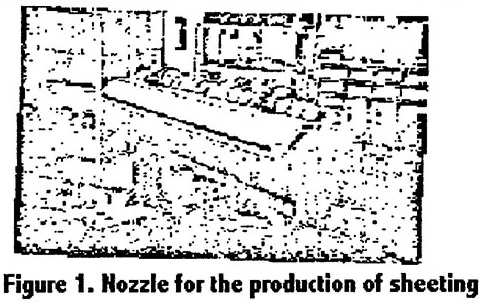
An extruder consists of two main parts: the part in which the material is melted and the part in which the material is shaped. After this stage the product leaves the extruder and is cooled. The shape of nozzle or die and the cooling process after the product is shaped are very important for the final product. Nozzles are available for producing sheeting, plates, blown films, assembling and coating.
Sheeting can be manufactured by extrusion. In view of the very great difference between the width and thickness of sheeting, and the special requirements which are set, a special extrusion technique is used. The nozzle is adjustable, which means that during the extrusion process the desired thickness can be determined very accurately at every point on the sheet or plate. However, this does not apply to the edges where different flow conditions are in force. As a result, the edges are usually somewhat thicker, and the thickness must be controlled by introducing a temperature gradient over the sheet.
After the sheeting leaves the nozzle it passes between rollers (hot or cold depending on the effect desired) to provide a smooth finish. The sheeting reaches its final form on these rollers. After it leaves the rollers, the edges with variable thickness are cut off and the sheeting is reeled into rolls (i.e. shrink film). Figure 1 gives a schematic representation of the extrusion of sheeting.
Figure 1
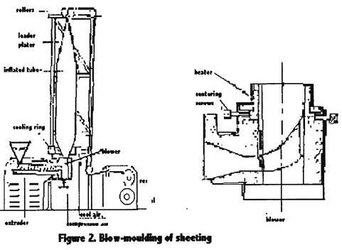
Blow-moulding of sheeting
Blow-moulding is a special technique for manufacturing hollow objects. A mandrel (core) is placed in the nozzle in open connection with the hollow space in the mould. The space can be brought under a given pressure through this connection. Ribs are needed to support the mandrel in the nozzle. The steam of melted materials is therefore cut by these ribs and welded together again behind them. If the welding is done too close to the point at which the sheeting leaves the nozzle, the seams remain visible and the material can even be weakened along these seams.
When sheeting or film is manufactured using the blow-mould technique, the hollow profile is inflated (Figure 2). The pressure which is required for this process is considerablly greater than that required for hollow profiles. In the later case, the resistance in the mould is sufficient to ensure positive pressure. Closure of the ends of the tube is only necessary in exceptional cases. When sheeting is being produced by blowing, the ends of the tube must be closed. This can easily be achieved by placing a set of rollers to nip the sheeting together. The volume of air between the head and the roller then determines the degree to which the material is inflated. In order to achieve a more homogeneous product, the mandrel remains stationary while a cooling ring turns around it. It is evident that this is essential when one considers that in a thin foil (e.g. 30 m), a difference of as little as 1 mm in thickness can lead to problems when the material is reeled up. Extra air which is applied around the nozzle is intended to ensure regular cooling and stabilization of the tube of plastic.
Figure 2
Calendering
A calender consists of a number of rollers (usually four) as shown in Figure 3. These rollers are usually set up in the form of an L or Z and heated by a separate oil, hot water or steam installation. The pre-heated mix is fed onto the first two rollers, and pressed out into a film (sheet). After this it is cooled on a third roller and reeled up. Before cooling, it is possible to print a pattern in the material.
Figure 3 - image no longer available.
When calendering PVC, a mixing roller is also needed to plastify the material before it runs through the rest of the calender.
Very wide film can be manufactured on a calender, but in practice it is not usually wider than about 2 m, since the costs of the calender rise disproportionally with greater widths. The minimum thickness which can be obtained is about 0.1 mm. A production rate of 25m per minute is normal.
Coating and laminating of geotextiles
For geotextile applications, a fabric or a membrane can be provided with a sealed film layer. A melted polymer is extruded through a nozzle in the form of a slit into a thin flat film. This film is applied to the material to be coated (the substrate). Pressure is applied to the material after which it is cooled and reeled up (Figure 4). It is possible not only to apply a film to a fabric substrate, but also to laminate a number of fabrics (and/or membranes) by applying a film between them (Figure 5). The film holds the layers together, and may be impervious to liquid and gases.
Figure 4
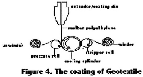
Figure 5 - image no longer available.
If the melting point of the substrate and the film is close to each other, the materials will hold together better, which will improve the ability of the coated fabric to handle forces. It is of great importance that the plastic used for the film has the correct temperature when it is pressed against the substrate.
Reinforced bituminous membrane
Reinforced bituminous membranes are built up from different elements, each with its own specific function, whether in the production process or in use. In most cases, the basis of the reinforced membrane is a substrate of polyamide fabric or polyester membrane, soaked in a bituminous mixture. Depending on the production process used, it is possible to include a glass membrane and/or a polyester film either as a substrate or as a filter. The polyester film also acts as a barrier to the penetration of plants and roots.
In the most common types of reinforced membranes, a layer of bituminous
mixture several millimeters thick is applied on either side of the
reinforcement layer. The membrane then receives a top layer, the
composition of which varies according to the requirements of the
application. The top layer can be:
- sand, to prevent sticking and to ensure roughness of the surface,
- slate chips, to provide UV protection,
- non-woven material, to improve mechanical strength (for example,
protection against puncture),
- film/sheet, to raise chemical resistance and act as a barrier to vegetation.
During the actual production process, the reinforcement layer is first soaked in a bitun-inous mixture and then brought together with a substrate. This substrate is then covered on both sides with a mixture, which is brought to the required thickness. Depending on the desired type, these layers can vary up to 3 mm. After this step, the top layers are applied.
At various stages in the production process the membrane is cooled depending on the temperatures in the manufacturing plant. This may be achieved with air, water or cooled rollers, and is done before the membrane is reeled up.
In order to prevent the membrane from sticking together on the reels, especially during storage and transport in high temperatures-a bituminous membrane paper or film is introduced between the material during reeling. Figure 6 shows a cross-section of a reinforced bituminous membrane.
Figure 6 - image no longer available.
PROPERTIES AND TEST METHODS
In this section the physical and mechanical properties of the following geomembranes are discussed: HDPE, LDPE, PVC, CPE, ECB and reinforced bitumen. By far the most well-known materials are HDPE and PVC. It is evident that many questions about the properties of these membranes remain unanswered, given the many test methods used to determine the same properties. The results of these different tests obviously cannot be compared with each other. Standardization of test methods is, therefore, necessary.
Thickness
The thickness of the geomembrane is measured continuously or by
sampling during the production process. By averaging and determining the
spread of thickness one can obtain an indication of the uniformity of the
membrane. The thickness of a geomembrane is of importance for the
following reasons:
- ensure sufficient impermeability to liquids and gases
- ensure that the geomembrane can adequately resist mechanical forces,
especially in the construction phrase
- ensure reliable techniques for welding the membrane sheets together
- allow the possibility of embossing the geomembrane, therefore increasing its friction between geomembrane and other materials.
Although it is usually assumed that the thickness of the geomembrane is uniform, in practice it does not always prove to be the case. Both thick and thin spots occur in the membrane as a result of the manufacturing process. Further, damage can occur during transport and handling at the construction site, as from scratches, dents and wear.
Variations in thickness can have extreme effects on stress-strain relationships. For instance, an HDPE membrane with a scratch which reduces the thickness by 25% will, in principle, suffer a 25% reduction in the yielding point. The strain at rupture will in this case be dramatically reduced from 7% to 14%.
Failure due to variation in thickness has been shown to occur in practice. Increase in thickness at spots in the membrane (e.g. welds) also lead to concentrations of tension. On the other hand, in reinforced membranes, where the barrier property is distinct from the strength, such increases in thickness are not problematic.
Tensile Properties
The curves of tensile stress verses strain of typical uniformly thick unreinforced geomembrane are shown in Figure 7. Curves having a yield point are typical of HDPE geomembranes.
Figure 7 - image no longer available.
For unreinforce geomembrane samples of uniform thickness, it is possible to standardize test results by dividing the force per unit width by the initial thickness (T) to obtain the stress s (s=N/t). A stress/elongation curve related to a given polymeric compound is valid for any geomembrane made of this polymeric compound, regardless of its thickness, while a force per unit width/elongation curve is only valid for one type of geomembrane (which includes thickness and polymeric compound).
In reinforce geomembranes the strength-strain behavior is not proportional to the thickness. The strength should be indicated as a force per unit width.
Much research into the two dimensional stress/strain relations of geomembranes has been carried out. Three-dimensional tests which give two-dimensional stress-strain relations have been shown to give a good indication of the manner in which geomembranes are subject to forces in practice.
Burst strength
A simple test for burst strength makes use of apparatus in which a sample is clamped between two concentric rings and forces are applied. The rings have a medium diameter of 500 mm. The sample is blown up using water or air in steps of 0.2 bar per two minutes, and the bulging and pressure are regularly measured.
The relationship between strain and tension force for nine different geomembranes given in Figure 8 are obtained with a more complicated test method than the one just mentioned. The thickness of the geomembrane is given in the figure, so it is possible to find the stress-strain relationship for these materials. The tests were carried out with two different HDPE materials, one PVC, one EPDM, one normal ECB material, one modified ECB, one PIB geomembrane and a bituminous geomembrane with fabric reinforcement and a polyester film. The figure shows that the two HDPE materials have strains at failure of 9% and 1.5%. This possible strain is 1% of the strain which is usually measured by one-dimensional stress-strain tests and about 50% of the strain at the tensile yield point.
Figure 8 - image no longer available.
These tremendous differences in strain at failure seem to be at least one of the reasons for failure of some geomembranes in practice. However, the difference in the failure load between one-dimensional tests and three-dimensional tests is not so high, particularly for materials with a low failure load.
Effect of Scrim reinforcement
The capacity of a reinforced geomembrane to absorb stress is a function of both breaking strength and elongation. By measuring the area under the load-elongation curve it is possible to optimize the balance between strength and elongation for in-service conditions.
With unreinforced membranes, the strain at failure rises sharply with higher temperatures, while the tensile strength is reduced. In reinforced membranes this occurs to a lesser extent, since the reinforcement is determinative.
When designing structures with reinforced geomembranes, one must take into account the fact that when the fabric has reached its strain at rupture, the membrane will, as a whole, have yielded. If the fabric suddenly breaks, in most cases the membrane will tear and lose its impermeable properties.
Friction
A critical element in the design process is the value of interface friction between components of the liner system. The design value will be the minimum value between any component of this liner system: soil, geomembrane or geotextile.
The various research efforts into the frictional properties of geomembranes indicate that friction does occur between membrane and soil. However, when using a smooth film (for instance, HDPE), it is in practice safer to assume a value of zero for friction. The stability of the soil mass which is placed on the geomembrane can be assured by roughening the surface of the film (raising the friction value), by spraying with a top cover or by embossing the film or by supporting the soil mass with a retaining structure at the bottom of the slope and by using geotextile matting, which is dug into the top of the slope.
There are mainly three techniques to produce textured geomembrane:
coextrusion, lamination and impingement (3):
- Coextruison: It uses a blowing agent in the moltened extrudate. As
the extrudate meets cool air and the confining pressure provided by the
extruding equipment is removed the blowing agent expands, results in a
roughened surface of the geomembranes.
- Lamination: An HDPE foam on a previously manufactured smooth sheet.
A foaming agent contained within melted HDPE provides a froth that
produces a rough textured laminate adhering to the previously
manufactured smooth sheet.
- Impingement: Hot particles are projected onto the previously manufactured smooth sheet, and thus texture to it.
Friction can be improved by using a geotextile between soil and membrane. One requirement is that the membrane and the textile are firmly attached to each other. In general, angular and multi-graded soils provide good friction on geomembranes with a low stiffness.
In contrast, the stiff, hard and smooth HDPE is fairly insensitive to soil type. Surface roughness is not induced by normal stress on the HDPE to soil interface. Relatively low friction ratios and efficiency indexes result. It is necessary to place another geotextile over the material in order to build a steep slope with HDPE.
Tests have been carried out to determine whether membrane/soil friction is affected if the soil mass is disturbed. These tests show that for HDPE membranes there is less friction on disturbed soils, and that greater displacements are necessary before frictional forces take effect.
The most common type of geomembrane in waste facility is manufactured from medium or high density PE. A typical geosynthetic system of a layered waste containment facility includes a geocomposites drainage and geomembrane-layer, geotextile cushion and filter, and geomembrane liners. Important characteristics with respect to stability is the shear resistance along the interface between various liners or cover system component. To increase the shear resistance of geomembrane, textured HDPE geomembranes having a roughened top and/or bottom surface has been developed (3).
Durability and Aging
The durability and aging of geomembranes are of major. Durability can be defined as the time during which the application functions normally. For a geomembrane, that means the time during which it will remain watertight in its environment and under different mechanical and chemical action. This is the most important point for the designer and owner. On the other hand, aging is the evolution of the properties of a product in time. Aging is necessary but not sufficiently to assess durability. Temperature, water action, UV light, microorganism, chemical products and thickness are all related to aging. Durability is related not only to aging, UV light, and water action, but also to puncturing, storage, folding, fatigue and welding (4).
PVC resins are chemically very stable, for correctly formulated geomembranes with good thermal and UV stability. Recent research shows that the durability of PVC membrane depends on the formulation and is directly related to the thickness of geomembrane (4). There is no degradation of PVC resin, except to a small depth at the exposed surface during the life of the geomembrane. Choice of plasticizier is also important in order to find the best compromise for an application.
Black Chlorosulfonated PE (CSPE) geomembrane have been exposed to
direct sunlight in Florida for up to 20 years. Observations of these
membranes shows that the membranes remain strong and flexible and are free
of any cracking or crazing on the exposed surfaces. This indicates that
many more years of good service should be expected. It shows that
significantly longer service life can be expected from membranes that are
used in installations where they are covered with soil (2).
The extent to which geomembranes are subject to wear is of particular importance in those cases where the material is subjected to such effects as moving sand or gravel in a canal or river or engineering plant during the construction phases. The resistance to these loads is expressed in terms of wear resistance. A test method is described below.
The sample is placed against the inside of a rotating cylinder. The cylinder is filled with a mixture of sand, gravel and water, and turned at a constant speed. The weight loss is measured after a number of revolutions, and the relationship between the number of revolutions and the weight loss of the various samples is plotted on a graph.
There do not appear to have been any comparative investigations into the wear resistance of PVC, CPE, ECB, HDPE, LDPE and bitumen.
Resistance to Puncture
The resistance of a geomembrane to puncture can be determined by an
impact test as described in standard testing method DIN 54307. The sample
is clamped between two rings with an internal diameter of 150 nun. A
plunger loads the sample at a constant speed of 60
10 mm/min. The
plunger has a diameter of 50 mm and a radius of curvature of 2.5 mm. The
maximum force which the sample can withstand is determined. It is not
advisable to use a thin geomembrane (< 1 mm) on rubble, since even with an
intervening layer of geotextile such a membrane is vulnerable.
Other Properties
Other important properties of geomembrane include tear strength, extensibility and permeability. Permeability
Geomembranes are used for their tightness character to various fluids. But it is never completely impermeable to all fluids and dissolved species. So different standard tests are necessary to characterize the membrane permeability. A sorption test and permeater cell method has been studied (5). The mechanism of diffusion in geomembrane is on molecular scale, which is different from porous media. Water molecules diffuse through narrow spaces between polymer molecular chains.
Flaws in Geomembrane
Flaws in geomembrane are common. Improper seaming is the main cause of most of the flaws, but puncture from the supporting soil or construction equipment may also cause flaws (6). Aging, interaction with leachats, UV lights, and high energy radiation may degrade geomembranes and cause flaws over long time periods,
INSTALATION CONSIDERATIONS
Preparation
Damage to the geomembrane must be avoided. This applies to transportation (good packing), loading and unloading (sufficient stiffness of the roll, for instance through use of a core and employment of appropriate equipment for handling), and laying of the membrane. The top 0.15 m of the subsoil must be free of sharp objects to avoid damage to the sheeting. The ground must also be stable, and access for installers and equipment must be good, that is the subsurface must remain flat.
Instructions regarding the accuracy of the finishing (e.g. 0.05 m per meter) and the carrying capacity of the structure should be set out. Before the membrane is laid, sharp cracks and corners (for instance in concrete structures) must be filled up or filed down.
Laying
The geomembrane is prefabricated in sections which are as large as possible in order to limit the number of welds which must be made. The prefabricated sections are, if possible, folded concertina-wise in one direction and rolled in the other direction around a core. Information on the manner in which the material has been folded and rolled is given on the folding specification. The sections can be lifted by the core. Each section numbered, and the number is repeated on the laying plan. This plan and the folding specification are used to determine the position of the sections on site. It is important to ensure that the correct side of the sheeting is placed face-up. The sections must be placed without tension, without folds, and must be anchored if necessary.
Joining
Geomembranes can be jointed in various ways. Various welding techniques may be used. Plastic membranes can be jointed using hot-element, hot-gas, or extrusion welding. Reinforced bitumen sheeting is jointed by pouring molten bitumen on a strip of at least 0.4 m along the edge of the sheet and pressing the second sheet onto the melted bitumen. Commonly-used methods to join various types of geomembranes are as follows:
- High-frequency welding,
- Hot-element welding,
- Hot-gas -welding,
- Extrusion welding,
- Solvent welding,
- Adhesives.
There are two methods for jointing bitumen membranes. The safer of the two is carried out with melted bitumen.
Cover Layers
If the geomembrane is to be covered, this must be done as quickly as possible after sections have been laid out and jointed together. While the ballast is being placed on the sheeting, constant inspection is necessary to check for any irregularities in the ballast (rubbish, twigs) and the positioning of the sheeting.
The geomembrane can be protected by various means, including the addition of a layer of soil. If gravel, concrete or open stone-asphalt is used, an additional layer, for instance a film, may be applied between membrane and cover to reduce the thermal and mechanical loads on the membrane.
Management and Maintenance
If a geomembrane is damaged this will in most cases mean that it is no longer waterproof. In such cases the water level should be lowered temporarily, so that assessing the damage does not have to be done underwater. With a drainage system, damage underneath the geomembrane can be traced.
Damages of any kind can be repaired as follows:
- after any protective cover removed, the geomembrane is cleaned.
- geomembranes which have been produced in-situ must then be resprayed with a new layer.
In prefabricated geomembrane welds which are not properly sealed, may repaire a patch. Damaged bitumen membrane, which is underwater, is repaired with mastic or closed stone asphalt after sand has been removed from the membrane.
REFERENCES
- John, N.W.M., Geotextiles. Chapman and Hall, 1987.
- Koerner,R.M., editor,
Durability and Aging of Geosynthetics.
Elsevier Applied Science, 1989.
- Stark, T., Williamson, A., and Eid, T.,
Journal of Geotechnical
Engineering. Vol.122, p. 197-203, March 1996.
- Fayoux, D.,
The 4th International Conference on Geotextile,
Geomembranes and Related Products. p.561-566, 1990.
- Faure, Y. and Pierson, P.,
The 4th International Conference on
Geotextile, Geomembranes and Related Products. p.543-548, 1990.
- Walton, J., Rahman, M., and Casey, D., Journal of Geotechnical and Geoenvironmental Engineering. Vol. 123, p. 534-9, June 1997.
Other Information:
http://trcs.he.utk.edu/textile/nonwovens/
Veldhuizen Van Zanten, R., Geotextiles and Geomembranes in Civil Engineering. 1986.
Visit our nonwoven education page.
Apparel Search
Add Your Company Contact
Us About Us Advertise
News Letter Legal
Help
Copyright ©
1999-2023 Apparel Search Company.
All Rights Reserved.
Buy Fashion
For The Holidays.