MELT BLOWN TECHNOLOGY (Textile Educational & Research)
Ramaiah Kotra & Haoming Rong Melt blowning is a process for producing fibrous webs or
articles directly from polymers or resins using high-velocity air or another
appropriate force to attenuate the filaments.
The melt-blown process
is one of the newer and least developed nonwoven processes. This process is
unique because it is used almost exclusively to produce microFibers rather
than Fibers the size of normal textile Fibers. Melt-blown microFibers
generally have diameters in the range of 2 to 4
: m, although they may be as small as
0.1: m and as large as 10 to 15
: m. Differences between melt-blown
nonwoven fabrics and other nonwoven fabrics, such as degree of softness,
cover or opacity, and porosity can generally be traced to differences in
filament size.
1. History
The basic technology to produce these microFibers was first developed under U.S. government sponsorship in the early 1950s. The Naval Research Laboratory initiated this work to produce microfilters for the collection of radioactive particles in the upper atmosphere. The significance of this work was recognized by an Exxon affiliate and a development program was initiated in the middle 1960s. Five years later, a patented prototype model successfully demonstrated the production of microFibers. At present, Exxon has developed most of the licenses and/or options to produce microfiber nonwoven and melt-blown equipment.
In the past 20 years there has been some activity outside of the Exxon technology and patents obtained by companies such as 3M. The company, 3M, has developed processes for making microFibers and blends of microFibers with textile denier Fibers that were apparently beyond Exxon patents. Exxon has continued to aggressively support melt-blown R&D through the years. The major portion of the Exxon-supported effort is now being conducted at the University of Tennessee, Knoxville. Some other North American major meltblown producers are Eastman Kodak, Hollingsworth and Vose, Kimberly-Clark, 3M, Fleetguard Filter.
2. Processing
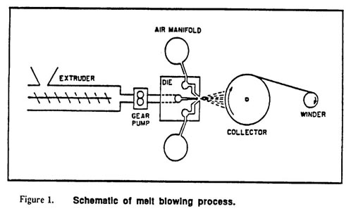
The most commonly accepted and current definition for the melt-blown process is: a one-step process in which high-velocity air blows a molten thermoplastic resin from an extruder die tip onto a conveyor or takeup screen to form a fine fiberous and self-bonding web.
The melt-blown process is similar to the spunbond process in that both convert resins to nonwoven fabrics in a single integrated process. The schematic of the melt blowing process is shown in Figure 1. A typical melt blowing process consists of the following elements: extruder, metering pumps, die assembly, web formation, and winding.
Figure 1
2.1 Extruder
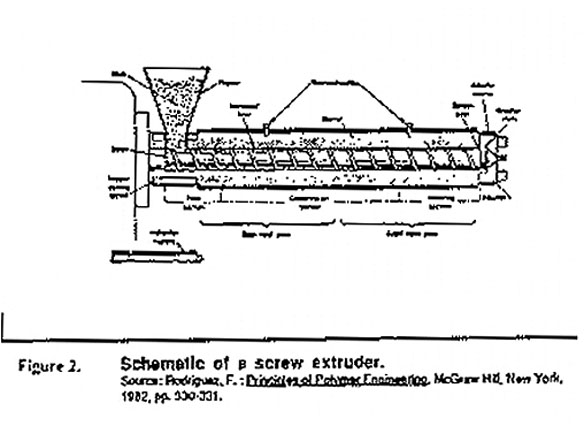
The polymer pellets or granules are fed into the extruder hopper. Gravity feed supplies pellets to the screw, which rotates within the heated barrel. The pellets are conveyed forward along hot walls of the barrel between the flights of the screw, as shown in Figure 2. As the polymer moves along the barrel, it melts due to the heat and friction of viscous flow and the mechanical action between the screw and barrel. The screw is divided into feed, transition, and metering zones. The feed zone preheats the polymer pellets in a deep screw channel and conveys them to the transition zone. The transition zone has a decreasing depth channel in order to compress and homogenize the melting polymer. The molten polymer is discharged to the metering zone, which serves to generate maximum pressure for extrusion. The pressure of molten polymer is highest at this point and is controlled by the breaker plate with a screen pack placed near the screw discharge, as shown in Figure 2. The screen pack and breaker plate also filter out dirt and infused polymer lumps. The pressurized molten polymer is then conveyed to themetering pump.
Figure 2
2.2. Metering Pump
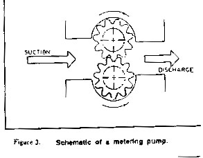
The metering pump is a positive-displacement and constant-volume device for uniform melt delivery to the die assembly. It ensures consistent flow of clean polymer mix under process variations in viscosity, pressure, and temperature. The metering pump also provides polymer metering and the required process pressure. The metering pump typically has two intermeshing and counter-rotating toothed gears. The positive displacement is accomplished by filling each gear tooth with polymer on the suction side of the pump and carrying the polymer around to the pump discharge, as shown in Figure 3. The molten polymer from the gear pump goes to the feed distribution system to provide uniform flow to the die nosepiece in the die assembly (or fiber forming assembly).
Figure 3
2.3. Die Assembly
The die assembly is the most important element of the melt blown process. It has three distinct components: polymer-feed distribution, die nosepiece, and air manifolds.
Feed Distribution
The feed distribution in a melt-blown die is more critical than in a film or sheeting die for two reasons. First, the melt-blown die usually has no mechanical adjustments to compensate for variations in polymer flow across the die width. Second, the process is often operated in a temperature range where thermal breakdown of polymers proceeds rapidly. The feed distribution is usually designed in such a way that the polymer distribution is less dependent on the shear properties of the polymer. This feature allows the melt blowing of widely different polymeric materials with one distribution system. The feed distribution balances both the flow and the residence time across the width of the die. There are basically two types of feed distribution that have been employed in the melt-blown die: T-type (tapered and untapered) and coat hanger type. Presently, the coathanger type feed distribution is widely used because it gives both even polymer flow and even residence time across the full width of the die.
Die Nosepiece
From the feed distribution channel the polymer melt goes directly to the die nosepiece. The web uniformity hinges largely on the design and fabrication of the nosepiece. Therefore, the die nosepiece in the melt blowing process requires very tight tolerances, which have made their fabrication very costly. The die nosepiece is a wide, hollow, and tapered piece of metal having several hundred orifices or holes across the width. The polymer melt is extruded from these holes to form filament strands which are subsequently attenuated by hot air to form fine Fibers. In a die's nosepiece, smaller orifices are usually employed compared to those generally used in either fiber spinning or spunbond processes. A typical die nosepiece has approximately 0.4-mm diameter orifices spaced at 1 to 4 per millimeters (25 to 100 per inch).
There are two types of die nosepiece used: capillary type and drilled hole type. For the capillary type, the individual orifices are actually slots that are milled into a flat surface and then matched with identical slots milled into a mating surface. The two halves are then matched and carefully aligned to form a row of openings or holes as shown in Figure 4. By using the capillary type, the problems associated with precise drilling of very small holes are avoided. In addition, the capillary tubes can be precisely aligned so that the holes follow a straight line accurately. The drilled-hole type has very small holes drilled by mechanical drilling or electric discharge matching (EDM) in a single block of metal, as shown in Figure 4.
Figure 4

During processing, the whole die assembly is heated section-wise using external heaters to attain desired processing temperatures. It is important to monitor the die temperatures closely in order to produce uniform webs. Typical die temperatures range from 2l5oC to 340oC.
Air Manifolds
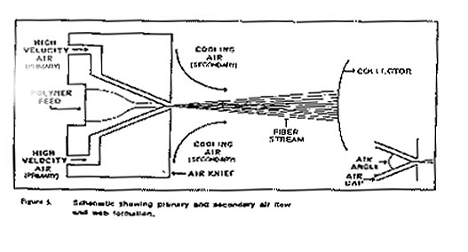
The air manifolds supply the high velocity hot air (also called as primary air) through the slots on the top and bottom sides of the die nosepiece, as shown in Figure 5. The high velocity air is generated using an air compressor. The compressed air is passed through a heat exchange unit such as an electrical or gas heated furnace, to heat the air to desired processing temperatures. The exits from the top and bottom sides of the die throughnarrow air gaps, as shown in Figure 5. Typical air temperatures range from 230oC to 360oC at velocities of 0.5 to 0.8 the speed of sound.
Figure 5
2.4. Web Formation
As soon as the molten polymer is extruded from the die holes, high velocity hot air streams (exiting from the top and bottom sides of the die nosepiece) attenuate the polymer streams to form microFibers. As the hot air stream containing the microFibers progresses toward the collector screen, it draws in a large amount of surrounding air (also called secondary air) that cools and solidifies the Fibers, as shown in Figure 5. The solidified Fibers subsequently get laid randomly onto the collecting screen, forming a self-bonded nonwoven web. The Fibers are generally laid randomly (and also highly entangled) because of the turbulence in the air stream, but there is a small bias in the machine direction due to some directionality imparted by the moving collector. The collector speed and the collector distance from the die nosepiece can be varied to produce a variety of melt-blown webs. Usually, a vacuum is applied to the inside of the collector screen to withdraw the hot air and enhance the fiber laying process.
2.5. Winding
The melt-blown web is usually wound onto a cardboard core and processed further according to the end-use requirement. The combination of fiber entanglement and fiber-to-fiber bonding generally produce enough web cohesion so that the web can be readily used without further bonding. However, additional bonding and finishing processes may further be applied to these melt-blown webs.
2.6. Bonding
Additional bonding, over the fiber adhesion and fiber entanglement that occurs at lay down, is employed to alter web characteristics. Thermal bonding is the most commonly used technique. The bonding can be either overall (area bonding) or spot (pattern bonding). Bonding is usually used to increase web strength and abrasion resistance. As the bonding level increases, the web becomes stiffer and less fabric-like.
2.7. Finishing
Although most nonwovens are considered finished when they are rolled up at the end of the production line, many receive additional chemical or physical treatment such as calendering, embossing, and flame retardance. Some of these treatments can be applied during production, while others must be applied in separate finishing operations.
3. Process Variables
Process variables can be classified into two categories: operational or on-line variableS and off-line variables. The on line variables include: polymer and its throughput, polymer/die and air temperature, die-to-collector distance, and quench environments. The off-line variables includes: hole size, die setback, air gap, air angle, web collection type, and polymer/airdistribution. The following represent some of the variables that must be controlled during melt blown production.
-Polymer type
-Polymer characteristics: molecular weight, melt viscosity, melt strength
-Extruder conditions: temperature, shear, polymer degradation
-Filtration
-Die tip geometry: hole diameter, air gap, die tip position
-Hot air conditions: volume, temperature, velocity
-Polymer conditions: temperature, flow rate, shear rate
-die conditions: temperature profile, gas flow rate profile, polymer flow rate profile
-Ambient air conditions: temperature, lack of turbulance
-distance from the die to the forming drum or belt
-Laydown conditions
Some efforts have been made to reduce the above variables to a few combined variables.
4. Web Characteristics and Properties
Uniformity
The uniformity of the web is controlled by two important parameters: uniform distribution of fiber in the air stream and proper adjustment of the vacuum level under the forming wire or belt. Non-uniform distribution of fiber in the air stream can result from poor die design and from non-uniform ambient airflow into the air stream. The vacuum under the forming media should be adjusted to pull the total air stream through the media and lock the Fibers in place. Generally, the closer the die is to the forming drum or belt, the better the web uniformity.
Product Characteristics
Melt-blown webs usually have a wide range of product characteristics. The main characteristics and properties of melt-blown webs are as follows:
1.Random fiber orientation
2.Lower to moderate web strength, deriving strength from mechanical entanglement and frictional forces
3.Generally high opacity (having a high cover factor)
4.fiber diameter ranges from 0.5 to 30 : m, but typically from 2-7 : m
5.Basis weight ranges from 8-350 g/m2 , but typically 20-200 g/m2
6.MicroFibers provide a high surface area for good insulation and filtration characteristics
7.Fibers have a smooth surface texture and are circular in cross-section
8.Most melt-blown webs are layered or shingled in structure, the number of layers increases with basis weight
The fiber length in a melt-blown web is variable; it can be produced in the range from a few millimeters to several hundred centimeters in length and usually exists over a broad range. The fiber cross-section is also variable, ranging from circular to a flat configuration and other variations.
Defects
Three of the major defects that occur in melt-blown production are roping, shot, and fly. Roping is caused by uncontrolled turbulence in the air-stream and by movement of Fibers during and after laydown. The defect is observed as a narrow, elongated, thick streak in the web and resembles a slightly twisted "rope". Shot are small, spherical particles of polymer formed during the blowing operation. Shot are generally caused by excessively high temperatures or by too low a polymer molecular weight. Fly is a defect that does not go directly into the web, but instead contaminates the surrounding environment. Fly is composed of very short and very fine microFibers not trapped on the drum or belt during laydown. This can be caused by too violent blowing conditions.
5. Process-structure-property
The web structure in a melt-blown product is essentially isotropic. This is not surprising since web formation is an air lay process. This means that the Fibers have a random distribution in terms of the machine direction (MD) and cross direction (CD). As a result, the physical properties will normally also be isotropic. If desired, the fiber orientation in the web can be skewed by the use of selected processing conditions.
A study done by Malken et al. (2) showed that polymer throughput of PP had a noticeable effect on the physical properties of resultant webs. The mean fiber diameter, tensile strength, initials modulus, stiffness and web density increase with increasing throughput. However, the decrease in both breaking strain and the energy required to break indicates the brittle nature of the web produced at higher throughput. Increasing fiber diameter was attributed to die swell and change in polymer-to-air ratio for a given airflow rate. Increase in airflow rate didn't result in any significant change in average fiber diameter. The die orifice size had only minimal effects on the average fiber diameter.
The Fibers that result in melt-blown webs are usually microFibers. The average fiber diameter can be controlled by the specific resin employed and the processing conditions selected. A typical microfiber can be as fine as 2 : m in diameter and less for some special applications. With such fiber fineness, the number of Fibers per unit weight is greatly increased. Further, the amount of fiber surface exposed is also substantially greater than that exposed in conventional webs. As a consequence, these characteristics can have a significant impact in a variety of product applications.
6. Polymer Type
The type of polymer or resin used will define the elasticity, softness, wetability, dyeability, chemical resistance and other related properties of formed Fibers. One of the advantages of melt-blown technology is to handle many different polymers as well as mixture of polymers. Some polymers, which can be melt-blown, are listed below. However, the list is not complete.
1.Polypropylene is easy to process and makes good web.
2.Polyethylene is more difficult to melt-blow into fine fibrous webs than is polypropylene. Polyethylene is difficult to draw because of its melt elasticity.
3.PBT processes easily and produces very soft, fine-fibered webs.
4.Nylon 6 is easy to process and makes good webs.
5.Nylon 11 melt-blows well into webs that have very unusual leather like feel.
6.Polycarbonate produces very soft-fiber webs.
7.Poly (4-methyl pentene-1) blows well and produces very fluffy soft webs.
8.Polystyrene produces an extremely soft, fluffy material with essentially no shot defects.
The most widely used polymer that has a high MFR is polypropylene. Polypropylene with its low viscosity has a low melting point and is easy to draw into Fibers. It comprises 70-80% of the total North American production (1).
The feasibility of melt-blowing original and recycled PET has also been studied (3). PET webs have a strong tendency to shrink, depending on the airflow rate used. PET webs produced at high airflow rate shrink more than those produced at low airflow rate because of their higher level of molecular orientation. Heat-setting of melt-blown PET webs or, alternatively, the use of PBT (poly-butylene terephalate) was suggested as a possible means of producing thermally stable melt-blown PET nonwovens.
7. Major Process Modifications
In the case of melt-blown web, additional process modifications can provide excellent flexibility in terms of designing new and novel products. Composite formation has been used extensively to supplement the limited physical strength of normal melt-blown webs and also to provide enhancement of other properties. This feature has been very effectively exploited in SMS structures based on a three-ply system consisting of Spunbond/melt-blown/spunbond plies to give an enhanced composite structure, supplementing the fiber and web properties of the melt blown with the strength and toughness of the spunbond surface fabrics. Lamination with a variety of other sheets and webs has also extended the range of properties achievable with melt-blown systems.
The combination of melt-blown Fibers with other Fibers has also been used effectively to design and enhance products. The most notable success of this is the Coform structures produced by Kimberly-Clark Corporation. These structures involve an intimate blend of melt blown Fibers and short woodpulp Fibers. By varying the ratio of the two fiber feeds, a broad range of products can be produced. Such Coform structures are often combined with a spunbond fabric on one or both surfaces to provide additional product versatility. Blends with other fiber types have also been produced, such as 3M's Thinsulate blends of polypropylene (PP) or polyester staple with melt-blown webs. In addition, the injection of solid materials, especially super-absorbent resins, has provided another range of interesting and useful products based on melt blown technology.
8. Applications
The melt-blown system is unique because the process generates a fine fiber not available to the other nonwoven processes. Micro-denier fiber (less than 0.1 denier per filament) is not really available as a nonwoven fibrous raw material. Hence, the melt-blown process, which can produce such a fiber, opens new vistas of products and applications. At the present time, the following market segments are successfully served by melt-blown products:
Filtration media
This market segment continues to be the largest single application. The best known application is the surgical face mask filter media. The applications include both liquid filtration and gaseous filtration. Some of them are found in cartridge filters, clean room filters and others.
Medical fabrics
The second largest meltblown market is in medical/surgical applications. The major segments are disposable gown and drape market and sterilization wrap segment.
Sanitary products
Meltblown products are used in two types of sanitary protection products - feminine sanitary napkin and disposable adult incontinence absorbent products.
Oil adsorbents
Melt blown materials in variety of physical forms are designed to pick up oily materials. The best known application is the use of sorbents to pick up oil from the surface of water, such as encountered in an accidental oil spill.
Apparel
The apparel applications of melt-blown products fall into three market segments: thermal insulation, disposable industrial apparel and substrate for synthetic leather. The thermal insulation applications takes advantage of microvoids in the structure filled with quiescent air, resulting in excellent thermal insulation.
Hot-melt adhesives
The melt-blown process has a special feature: it can handle almost any type of thermoplastic material. Thus, the task of formulating a hot-melt adhesive to provide specific properties can be greatly simplified by using the melt blown system to form the final uniform adhesive web.
Electronic specialties
Two major applications exist in the electronics specialities market for melt blown webs. One is as the liner fabric in computer floppy disks and the other as battery seperators and as insulation in capacitors.
Miscellaneous applications
Interesting applications in this segment are manufacture of tents and elastomeric nonwoven fabrics which have the same appearance as continuous filament spunbonded products.
9. Complexity of Melt Blown Technology
The melt-blown process is a complex one that involves turbulence, which is poorly understood by the scientist even today. Isolation of experimental factors is difficult because of highly variable interaction. The multi-filament environments and factors such as humidity of the processing room and quench air temperature wildly change boundary conditions (4).
The processing window for successfully melt-blowing polymers is very limited. In order to produce webs with acceptable quality, one has to be in the right range of process parameters and the range varies between polymers. Unlike melt-spinning, there is almost virtually no control over the individual filaments in melt-blowing. It is very difficult to predict structure/property of melt-blown filaments since the isolation of variables is very difficult in a multi-filament environment.
Melt-blown products are difficult to compare to other nonwoven products because they are quite different in nature and function. Most nonwoven fabrics are designed to function similarly to woven or knit fabrics and generally can be replaced with such fabrics, although usually at a performance and /or financial penalty. With limited exceptions such as some wipes, melt-blown products are not designed to function as fabrics. They are generally manufactured in sheet form but lack the physical strength of conventional woven or nonwoven fabrics.
On the other hand, despite extensive research and development in this area, there is a paucity of published research studies, mainly due to the secretive and competitive nature of the work. However, there is considerable patented literature available.
10. Melt-blown Vs Spunbond
The spunbond and melt-blown processes are somewhat identical from an equipment and operator's point of view. The two major differences between a typical melt-blown process and a spunbond process that uses air attenuation are: (1) the temperature and volume of the air used to attenuate the filaments and (2) the location where the filament draw or attenuation force is applied.
A melt-blown process uses large amounts of high-temperature air to attenuate the filaments. The air temperature is typically as high or higher than the temperature of the polymer. In contrast, the spunbond process generally uses a smaller volume of air close to ambient temperature to apply the attenuation force.
In the melt-blown process, the draw or attenuation force is applied at the die tip while the polymer is still in the molten state. Application of the force at this point is ideal for forming microFibers but does not allow for polymer orientation to build good physical properties. In the spunbond process, this force is applied at some distance from the die or spinneret, after the polymer has been cooled and solidified. Application of the force at this point provides the conditions necessary for polymer orientation and the resultant improved physical properties, but is not conductive to forming microFibers.
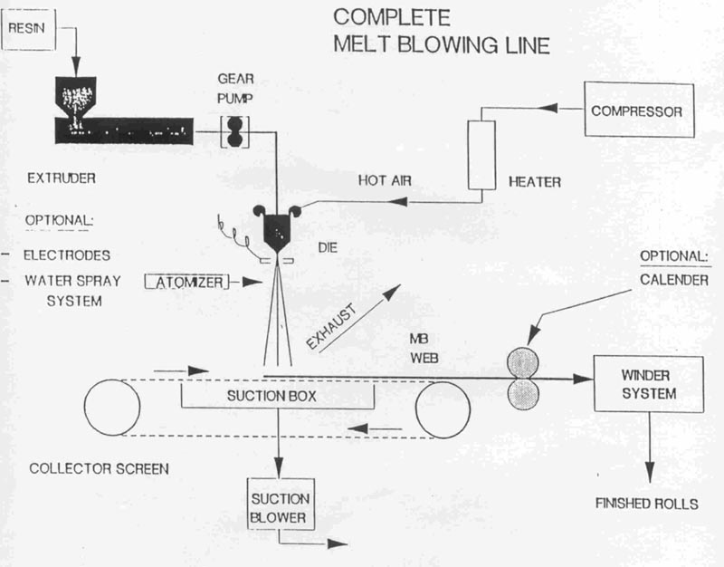
11. Process Equipment
Although the melt-blown process is conceptually simple, high-quality webs at commercial scale require precisely designed and fabricated equipment. In a manner similar to spunbond technology, many melt-blown web-manufacturing companies such as3M and Freudenberg have developed proprietary technology. Most of the melt-blown processes in the market now are based on the Exxon process. The process equipment layout, which can be vertical or horizontal, is simpler and more compact than that of spunbonding. A vertical layout is preferred when multiple dies are used, but horizontal layout is preferred when a single die is used. The vertical space requirement, usually a minimal of 20 ft., depends on the die-to-collector distance. The horizontal space requirements depend on the total width of the die and end product requirement. Usually three times the vertical space is the minimal requirement for a horizontal space (1). In summary, a schematic follows that shows components of a complete melt blowing line.
Figure 6
12. Economics of Melt-blown Webs
The economics of melt-blown process is influenced by many factors such as energy, capital investment, and production speed conversion. With respect to energy, the melt-blown process requires more energy than does the spunbond process. A typical melt blowing process consumes about 7-8 kWh/kg of polymer process, while a typical spunbond process consumes 2-3 kWh/kg. Melt-blown processing is more energy-intensive because of compressed hot air is used for fiber attenuation. About 70% of total energy used for hot air. This result in a high production cost. Typically, a 2.0-oz PPspunbonded web cost US $0.12 to $0.24/yd2, while a melt-blown equivalent is $0.32-$0.37/ yd2 (1).
Initial capital investment of a melt-blown line is much lower than that of spunbond line. Typically, the later is 3-4 times higher than the former. But the production speed of spunbonding is inherently faster than that of melt-blowing.
13. The potential for meltblowing
The melt blown technique for making nonwoven products has been forecast in recent years as one of the fastest-growing in the nonwovens industry. With the current expansion and interest, it cannot be questioned that meltblown is well on its way to becoming one of the major nonwoven technologies. Technical developments are also on the horizon that will increase the scope and utility of this technology. The application of speciality polymer structures will no doubt offer new nonwoven materials unobtainable by other competitive technologies. The considerable work to modify the blowing step to something more akin to spraying is also going to have an impact on this technology and the products derived from it. So a strong and bright future be forecasted for this technology.
REFERENCES:
- Malkan, S., Tappi Journal, Vol.78, No.6, pp185-190, 1995.
- Malkan, S.R. and Wadsworth, L.C., IND JNR, No.2, pp21-23,1991.
- Bhat, G.S., Zhang, Y., and Wadsworth, L.C., Processing of the Tappi
Nonwoven Conference, Macro Island, FL, May,
pp61-68, 1992.
- Vasanthakumar, N., Dissertation, Dimensional Stability of Melt-blown
Nonwovens. The University of Tennessee,
May,1995.
Additional Sources of Information:
Visit our nonwoven education page.
Apparel Search
Add Your Company Contact
Us About Us Advertise
News Letter Legal
Help
Copyright © 1999-2023 Apparel Search Company.
All Rights Reserved.
Buy Fashion
For The Holidays.